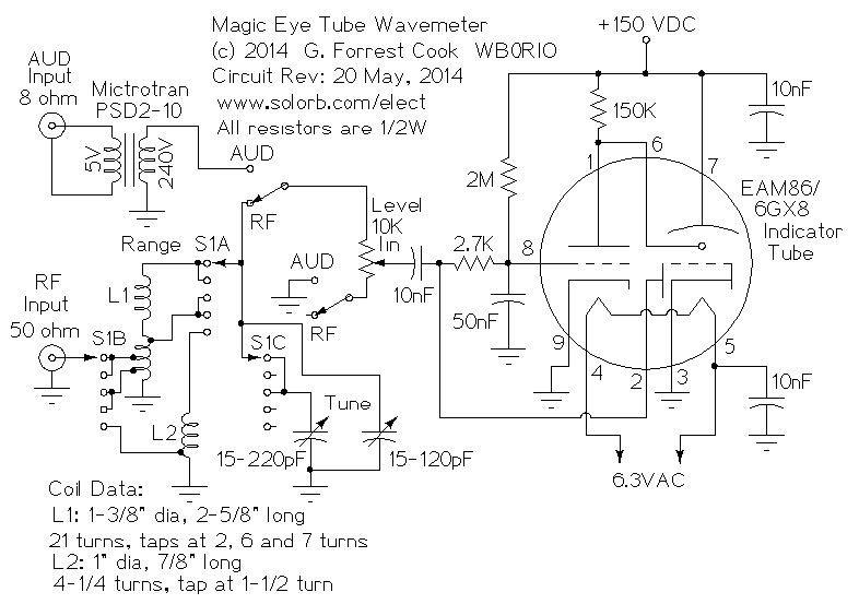
Magic Eye Tube Wavemeter
Magic Eye Tubes and Tuning Indicators Good eye tubes such as 6E5 and 6U5 are getting harder to find. Many of the old ones have lost most of their green glow. You can increase the green by a slight modification of the circuit. These tubes were originally specified for operation at about 250 volts.

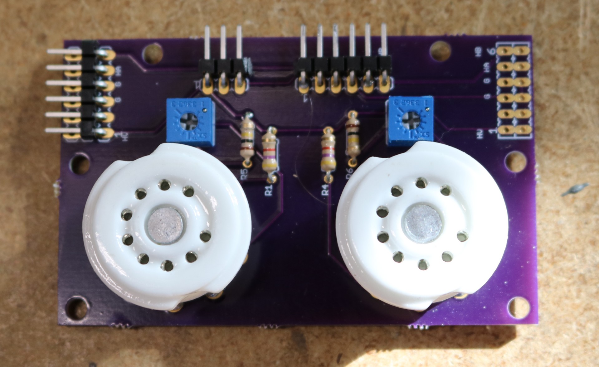
Magic Eye Emulation with Arduino Electroagenda
This makes the magic eye tube a perfect choice to display a one dimensional V-U characteristic of a given wave in real time. THE POWER SUPPLY CIRCUIT: The PSU circuit, basically employs a 555 timer to set a stable oscillation frequency for the MOSFET, which in turn uses the property of inductors, that whenever an abrupt change of current occurs, a voltage spike is induced on the output.

Magic eye working circuit YouTube
"Magic Eye" emulation project written and developed by Konstantin Dorohov (USA). The recorders and receivers of my youth used the now defunct tube level indicators or "magic eye" on 6E1P or 6E5C lamps. Now is the time for nostalgia for the "old days" and you can buy assembled indicators on aliexpress or amazon.
The H.P. Friedrichs (AC7ZL) Homepage
Design History 101 The Hidden History of Magic Eye, the Optical Illusion That Briefly Took Over the World How a 1990s op-art phenomenon went from a tech-spec magazine to households everywhere Words by Liz Stinson Published on July 1st, 2022 01 © 2018 Magic Eye Inc.
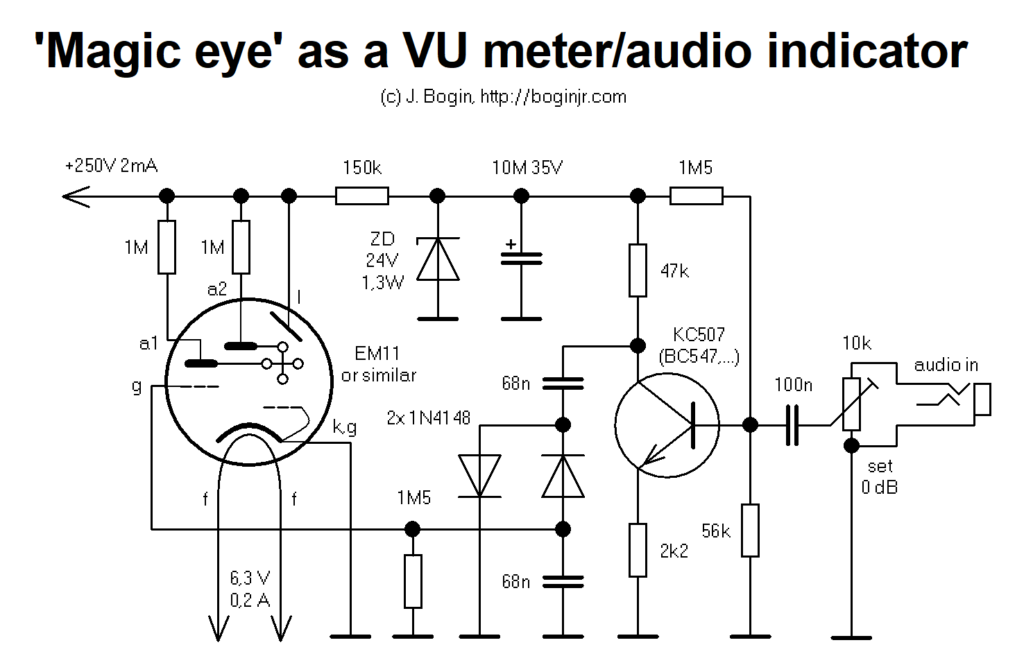
Magic eye tuning indicator as a VU meter BOGIN, JR.
Although the magic eye circuit is simple, this project requires connecting to a high-voltage current source within the chassis of an antique tube radio. For that reason, I consider it suitable only for advanced builders and radio restorers.

Magic Eye Winker • The senseless circuit YouTube
Find the deal you deserve on eBay. Discover discounts from sellers across the globe. No matter what you love, you'll find it here. Search Magic eye poster and more.
Magic Eye Tube PC Monitor Dr. Scott M. Baker
This is a Japanese Toyo tube from the 1970s.I have a second channel: https://www.youtube.com/channel/UCN3Dgu6CVBcecDkc5DmIIqw

Magic Eye Circuit Using 4049 IC
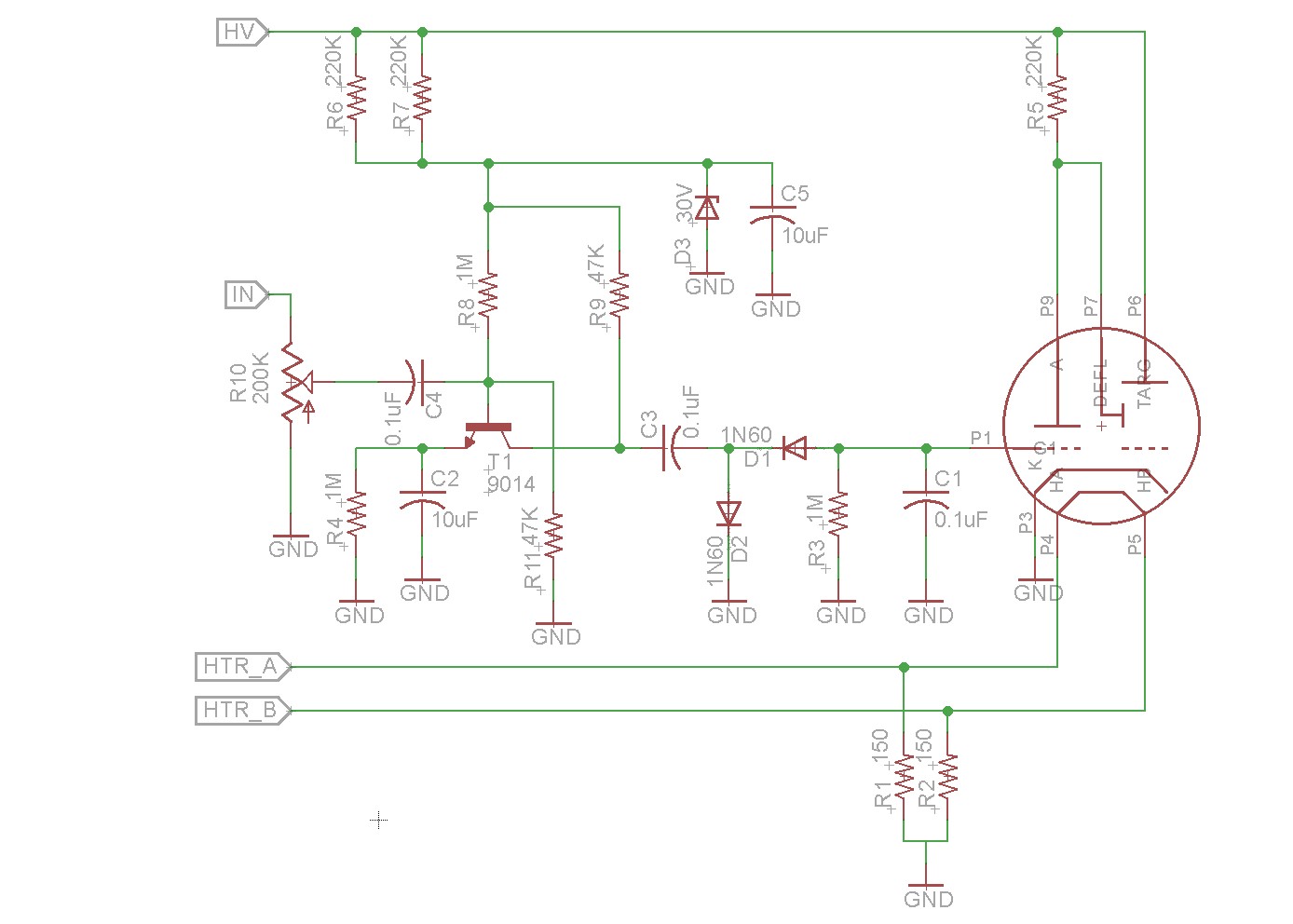
The operation of this circuit is quite straightforward and can be used with other tuning indicator tubes in general. There's an anode supply of 250 volts d.c., functioning also as a voltage source for the grid (current limited and stabilized to 24 volts, by means of a small Zener diode).
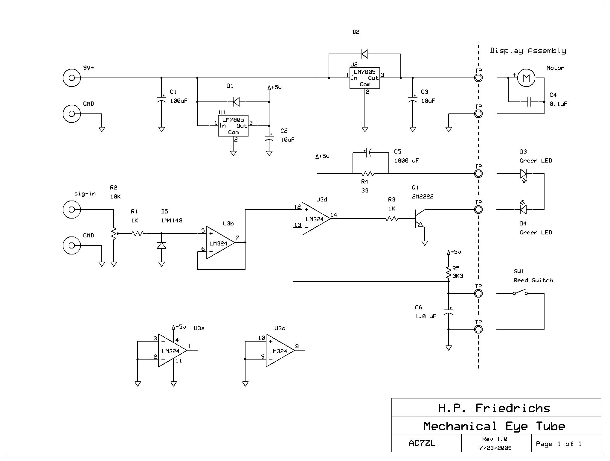
The H.P. Friedrichs (AC7ZL) Homepage
With the ghostly green glow of its circular face, magic eyes stood in for more expensive moving-coil meters for things like tuning indicators and VU meters. And while they may be getting hard to.

Magic Eye Tube Audio Spectrum Analyzer Dr. Scott M. Baker
These are mostly miniature Cathode Ray Tubes (CRT) with an electrode (or several) to vary the size of a shadow according to signal level. One Magic Eye works in a similar way to a VFD (Vacuum Florescent Display), the DM70 / DM71. The DM160 and the similar Russian iv15 are not Magic Eyes, just VFD type indicators.
Magic Eye Tube interfacing with a Raspberry Pi Dr. Scott M. Baker
Fuzzy is sometimes associated with an increased AC content on the input grid (ie. AC plus DC content). Perhaps there is a loading aspect of the magic eye circuit on the signal level being sensed, or a change to the rectification/filter time response (due to on-voltage or series resistance or reverse leakage) - which is modified by the change in diode type.
Magic Eye using 555 Timer IC
An anode held a coating that would glow when hit with electrons — usually green, but sometimes other colors. Later tubes would show a stripe going up and down the tube instead of a circle, but you.

Magic eye circuits for 6E5 Google Groups
A magic eye tube or tuning indicator, in technical literature called an electron-ray indicator tube, [1] is a vacuum tube which gives a visual indication of the amplitude of an electronic signal, such as an audio output, radio-frequency signal strength, or other functions. [1]
Magic Eye tubes help/suggestions Meter Circuit for FUN
The magic eye circuit is based on NOT gate CD4049 IC. In this circuit, we are utilizing only 1 gate of IC. To understand the working you should know about the truth table of NOT gate which is: In NOT gate, we will get output as logic high when logic zero is provided and we will get logic zero when logic1 is provided in input.

Magic eye generator
IC 4049 (Hex Inverter Buffer) IC 4049, also known as hex inverter buffer IC, is used for the conversion of high logic level to low. 4049 IC can handle two TTL loads as it has higher input supply voltage with a current rating of 1mA. The main application of IC 4049 is creating voltage multiplier circuit. It can also be used for square wave.
Octoglow VFD Geiger counter and magic eye Słomkowski's technical musings
The tester uses an eye tube (sometimes called a magic eye tube) as an indicator. A 40 MHz oscillator produces a signal that finds open and shorted capacitors. You can also measure resistance,.
